LS-B
Low Silhouette Vertical Basic
Designed for furred in, under the window applications, the low silhouette vertical basic (LS-B) stands only 15" high and accommodates a field furnished and installed decorative enclosure that conceals the unit. The basic unit consists of a chassis, fan deck, drain pan, throwaway filter and a top-discharge duct collar.
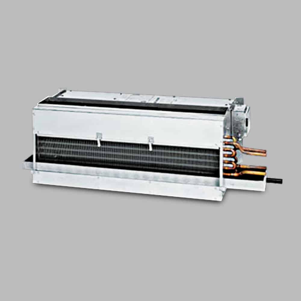
Only 15" tall
Height
Top discharge duct collar
Discharge
300 PSIG
Max Working Pressure
180°F
Max Water Temp
Technical Details
Features & Specifications
Chassis
All unit chassis shall be fabricated of heavy gauge cold rolled steel panels. All exterior panels shall be insulated with 1/2" thick, 3.35 pound per cubic foot, dual density fiberglass insulation rated for a maximum air velocity of 3600 f.p.m. Insulation shall conform to UL 181 for erosion and NFPA 90A and 90B for flame spread (25) and smoke developed (50) rating per ASTM E-84 and UL 723 and CAN/ULC, S102-M88.
Available Options
- 16 gauge front panel on exposed units with recessed stamped louver discharge grille
- Architectural grade single deflection discharge grille with powder coated paint finish
- Architectural grade bar discharge grille with powder coated paint finish
- Foil faced insulation meeting ASTM Standards C-665 and C-1136 for biological growth
- Elastomeric foam insulation with antimicrobial performance rating of 0 per ASTM G-21
Outside Air
Provide a manual or two position motorized outside air damper integral to the unit.
Available Options
- Aluminum outside air wall box with louvers and integral bug screen and weep holes
Fan & Motor
Unit fan shall be dynamically balanced, forward curved, DWDI centrifugal type constructed of heavy gauge galvanized steel for corrosion resistance. Motors shall be high efficiency, permanently lubricated sleeve bearing, permanent split-capacitor type with UL and C-UL listed automatic reset thermal overload protection and three separate horsepower taps. Single speed motors are not acceptable.
Drain Pan
Condensate drain pans shall be single wall, heavy gauge galvanized steel for corrosion resistance, and extend under the entire coil section. Drain pans shall be of one-piece construction and be positively sloped for condensate removal. The drain pan shall be externally insulated with fire retardant, elastomeric foam insulation carrying no more than a 25/50 Flame Spread and Smoke Developed Rating per ASTM E-84 and UL723.
Available Options
- Primary drain pan constructed entirely of heavy gauge type 304 stainless steel
- Silent switching devices for fan speeds (mercury and quiet relays not acceptable)
Coil
All cooling and heating coils shall optimize rows and fins per inch to meet the specified capacity. Coils shall have seamless copper tubes and shall be mechanically expanded to provide an efficient, permanent bond between the tube and fin. Fins shall have high efficiency aluminum surface optimized for heat transfer, air pressure drop and carryover. All coils shall be tested at 350 PSIG air pressure under water, and rated for a maximum 300 PSIG working pressure at 180°F maximum water temperature.
Available Options
- Automatic air vents in lieu of manual air vents
Electric Heat
Electric resistance heating assembly as an integral part of the fan coil unit, with the heating capacity, voltage and kilowatts scheduled. The heater assembly shall be rated for installation on the fan coil unit and be located so as not to expose the fan assembly to excessive leaving air temperatures. The heater and unit assembly shall be listed for zero clearance and meet all NEC requirements, and be UL listed with the unit as an assembly.
Available Options
- Silent switching devices for electric heat (mercury and quiet relays not acceptable)
Piping Package
Factory assembled valve piping package consisting of a 2 or 3 way, on/off, motorized electric control valve and two ball isolation valves. Control valves shall be piped normally closed to the coil. Maximum entering water temperature on the control valve shall be 200°F, and maximum operating pressure shall be 300 PSIG.
Available Options
- 3-wire floating point modulating control valve (fail in place)
- High pressure close off actuator for 2 way on/off control valve
- TRACvalve zone control system
Filter
All units shall be furnished with a minimum 1" nominal glass fiber throwaway filter. Filters shall be tight fitting to prevent air bypass. Filters shall be easily removable from the return-air opening without the need for tools or removal of the front panel.
Available Options
- 1" pleated filter (MERV 6)
- Decorative stamped louver grille in the return air opening
WARNING: This product can expose you to chemicals including epichlorohydrin which is known to the State of California to cause cancer and birth defects and/or other reproductive harm. For more information go to p65warnings.ca.gov
Related Products
Also Available
Ready to Specify?
Our team of experts can help you select the right fan coil configuration for your project.